Online bolt torque calculator ( UTS and VDI 2230)
Online bolt torque calculator UTS
How it works

Where
- $P$ : pitch of the thread in milimeters; it has been obtained from ASME B1.1-2003 (Unified Inch Screw Threads)
- $\mu_G$ is the coefficient of friction in the thread (in this case we have considered $\mu_G$ and $\mu_K$ equal and obtained from UNE 17-108-81)
- $\mu_K$ is the coefficient of friction in screw head (in this case we have considered $\mu_G$ and $\mu_K$ equal and obtained from UNE 17-108-81)
- $d_2$ pitch diameter of the bolt head in mm; it has been obtained from ASME B1.1-2003 (Unified Inch Screw Threads)
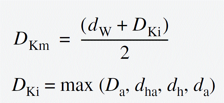
- $D_{Km}$ Effective diameter for the friction moment at the bolt head or or nut bearing area and it is defined by the following expression
- $D_{Ki}$ is the inside diameter of the bearing area,we have considered the same as $d_2$ and it has been obtained from ASME B1.1-2003 (Unified Inch Screw Threads)
- $F_{Mzul}$ Permissible assembly preload defined by the following expressions
- $\nu$: utilization fator of yield point stress (limit of full plasticization of th cross section at risk)durin tightening. It is defined by user in the proof load percentage
- $R_{p0,2}$ 0,2% proof strength of the bolt according to DIN EN ISO 898-1; in this case we have used the values of proof load from the standards SAE and ASTM and converted to the proper units $N/{mm}^2$
- $A_0$ Appropriate minimum cross sectional area of the bolt
- $d_2$ pitch diameter of the bolt head in mm; it has been obtained from ASME B1.1-2003 (Unified Inch Screw Threads)
- $d_0$ diameter at the relevant smallest cross section of the bolt; from the ASME B1.1-2003 (Unified Inch Screw Threads; Minor Diameter)

Where


Where
$Note 1:$ In the case that the geometry standard it is unknown then the progrma assigns to the Dkm value the average of several screw standards. It is not so significant in the end result.
$Note 2:$ In the case of do not know the constact surfaces material the calculator willa assign a friction coefficient of 0,1 (($\mu$) is 0,1)
Another function is to help to check the maintainability. If you introduce the screw standard and thread size you will have the link to the recommended 3D models tools in order to check the required space to apply torque and to remove the screw. This will help to check that the design is easy to mantain and prevent future redesign process during the assembly. You only have to insert the tool in your 3D model and you will see that the bolt head clearance for the wrench, spanner or socket is enough.
Instructions
1) Enter thread diameter nominal value in section Thread Size. Click on info button for more info
2) In section Head Size and Type either select one fastener ISO with the "Select Standard for Type" option or enter manually the type and whether the fastener is socket or not in the right part of the page, once you have selected Custom option.
3) Enter strength class of the fastener. Click on info button for more info
4) In section Coefficient of Friction either select one lubrication condition (faster and surface combination) with the "Select Friction condition" option or enter manually or let the default value in the right part of the page, once you have selected Unknown option.
5) Click on button calculate, and the calculated torque will appear below.


